


Resolver phase measurement system
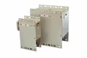
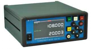
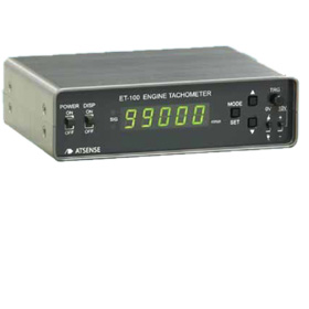
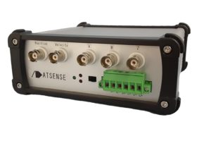
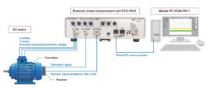
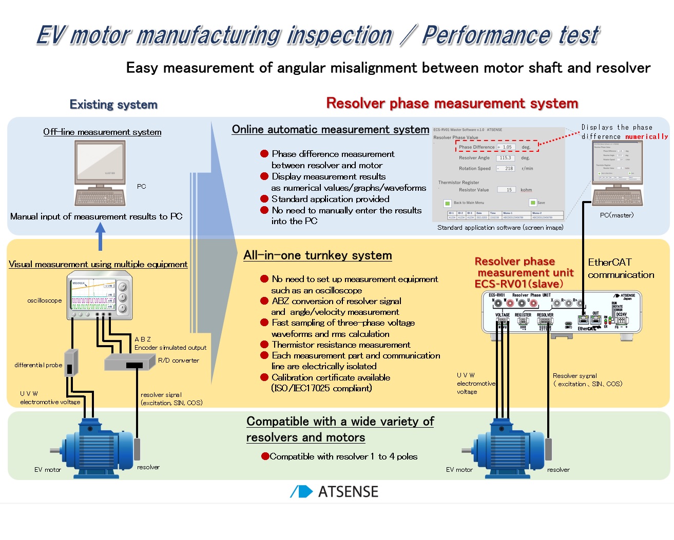
The ATSENSE ECS-RV01/ECM-RV11 Resolver Phase Measurement System delivers highly reliable resolver phase and counter-electromotive voltage analysis for EV motor development. By directly measuring 3-phase back-EMF and resolver signals, it identifies the precise magnet position, enabling efficient drive control. Features include waveform and numeric display, resistance and velocity measurement, EtherCAT synchronization for multi-unit setups, and ISO/IEC17025-calibrated accuracy. This robust solution supports advanced motor testing and validation in demanding R&D environments.- Simultaneous display of numerical values and waveforms for phase difference measurement
- Various measurements such as resolver phase, angle/velocity, thermistor resistance value, and three-phase effective value
- CSV data for measurement conditions and measurements, hard copy of screen
- Calibration certificate can be issued for unit voltage value ISO/IEC17025
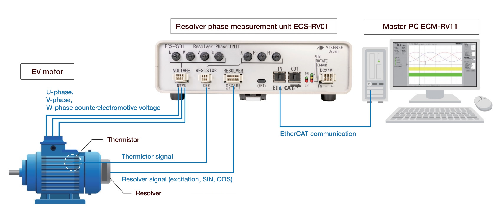
- Guarantee for the synchronicity of multi-unit data via EtherCat communication
※This system uses EtherCAT communication, and the connected EtherCAT slave units can maintain synchronicity.
Comparison between the existing method of resolver phase measurement and this system
| Resolver interface | |
| Target resolver | 1-phase excitation 2-phase (SIN, COS) output resolver |
| Resolver excitation signal | R1・R2 7Vrms Excitation frequency selectable from 10kHz/20kHz |
| Input from resolver | Sine input (S2,S4) and Cosine input ( S1, S3) Selectable input gain and shaft angle multiplication (×1 to ×4) |
| Encoder simulated output | A-phase, B-phase, Z-phase Maximum phase difference measurements: 1200r/min |
| Angular position output | Resolution±0.09° Maximum error when resolver is stationaryat a standstill±0.4° |
| Rotational velocity | Calculated from encoder simulated signal A-phase and B-phase 0 to 5000r/min for X2 resolver |
| Connector | 6-pin spring type terminal block connector 2.5mm pitch 1 row |
| Counter electromotive voltage input | |
| Input voltage | Three-phase AC100Vrms or less between phases Temperature deviation ±0.02V Instantaneous value accuracy ±0.07V |
| Conversion speed | 100kSPS (signed 16bit data) |
| Insulation spec. | Three-phase collective ground (FG) AC2000V for 1 minute |
| Connector | 4-pin spring type terminal block connector 2.5mm pitch 1 row |
| Resistance measurement | |
| Resistance range | 100Ω~150kΩ Resistance value error ±1.5% (1kΩ to 150kΩ), ±4% (100Ω) |
| Assumed usage | Connect a thermistor to measure temperature (Conversion from resistance value to temperature is performed by the master) |
| Connector | 2-pin spring type terminal block connector 2.5mm pitch 1 row |
| EtherCAT port(IN/OUT) | |
| Connector | RJ45 socket IN port/OUT port 1 each |
| Protocol | EtherCAT slave |
| Connection cable | Ethernet category 5 or higher, double shield, straight wiring Possible to be prepared by users |
| Transmission speed | 100Mbps |
| Sync mode | Fixed at 1ms |
| General specifications | |
| RoHS Directive | European RoHS1 directive compliant |
| Power supply | DC24V±20%、6700mA max 3-pin spring type terminal block connector 3.5mm pitch 1 row |
| Electrical isolation | Electrical isolation between the following groups A/D input interface (counter electromotive voltage input) Resolver interface/internal circuit- EtherCAT connector (IN and OUT), case, FG (ground)- Power supply (DC24V) |
| Ambient temperature | -25℃~+60℃ |
| Ambient humidity | 95% RH or less (no condensation) |
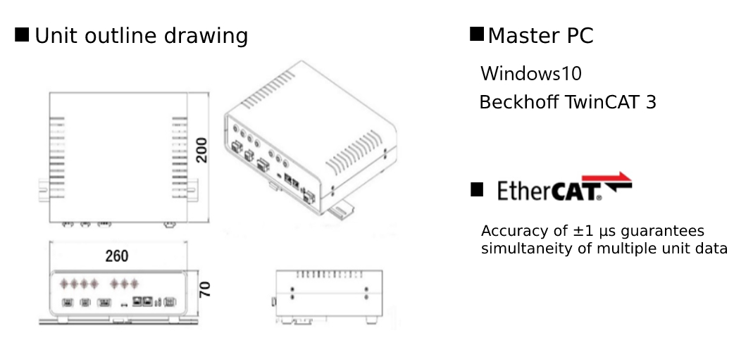
| External dimensions | 260(W)×70(H)×200(D) mm Not including protrusions |
| Weight | about 1600g |