


Crank-Angle Reference Signals Without an Added Encoder
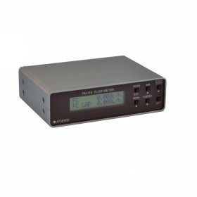
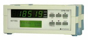
The ATSENSE CPM-100 converts existing crankshaft position sensor pulses into a 360-pulse-per-revolution (360 p/r) angle reference for automotive engine research and development.
Unlike simple fixed-period multiplication, the CPM-100 adjusts the output pulse period to changes in engine rotational speed. This method helps maintain the input-to-output phase relationship during speed fluctuations, reducing accumulated crank-angle deviation.
360 p/r
CPM-100 angle output
180/360/720
CPM-100A selectable p/r
10–20 kHz
Crank signal input frequency
1 p/r
TDC reference output
The unit accepts crank sensor signals from toothed wheels with supported missing-tooth patterns and provides a 1 p/r top-dead-center (TDC) reference in addition to the multiplied angle output. The input frequency range is 10 Hz to 20 kHz.
The base CPM-100 provides a 360 p/r angle output. The related CPM-100A supports selectable 180, 360 or 720 p/r outputs, including 0.5° pulse spacing at 720 p/r. Confirm the required model before specifying the output resolution.
Encoder-Free Crank Reference
Uses the vehicle crankshaft position signal instead of requiring a separately installed optical encoder.
Speed-Fluctuation Correction
Adjusts multiplied pulse spacing to account for changing crankshaft rotation speed.
Missing-Tooth Compatibility
Handles specified crank trigger plates with missing or additional teeth.
360 p/r Base Model
CPM-100 generates a 360-pulse-per-revolution crank-angle signal.
CPM-100A Output Selection
The CPM-100A variant offers 180, 360 or 720 pulses per revolution.
Analog and TDC Outputs
Provides a 1 p/r TDC reference and a 0–10 V frequency-to-voltage output.
Combustion Pressure Analysis
Provide the crank-angle pulse reference used to align combustion-pressure data.
Engine Vibration Analysis
Supply a standardized angular reference for rotationally synchronized vibration measurement.
Crankshaft Timing Evaluation
Examine engine events against a reconstructed per-revolution crank-angle reference.
Belt Displacement Studies
Correlate belt displacement with crank-angle position during engine tests.
Missing-Tooth Crank Systems
Generate continuous angle pulses from compatible toothed-wheel sensor inputs.
Engine Dynamometer Research
Integrate synchronized crank pulses into engine R&D data acquisition arrangements.
| Specification | Value |
|---|---|
| Crank input frequency | 10–20,000 Hz |
| Crank input connector | BNC receptacle and screwless terminal block |
| Input signal format | Sine wave (0 V trigger) or square wave (+2.5 V trigger) |
| Trigger slope | Rising or falling |
| Input low-pass filter | OFF / 20 kHz (−3 dB) |
| Input pull-up | OFF / ON (terminal block only) |
| Sensor supply | +12 V, 80 mA |
| Input resistance | 100 kΩ |
| Input voltage | ±50 V; absolute maximum rating ±100 V |
| Wave-shaping output | TTL, 0–5 V |
| Multiplied angle output – CPM-100 | 360 p/r |
| Multiplied angle output – CPM-100A | 180 / 360 / 720 p/r selectable |
| TDC output | 1 p/r |
| Multiplied output connectors | 2 BNC outputs |
| Multiplied output level | TTL, 0–5 V |
| Output polarity | Positive or negative logic |
| F/V output | 0–10 V; 1 BNC output |
| F/V refresh | Every 1 ms |
| Moving average | 1–500 |
| Frequency timing reference | 40 MHz |
| Power | 9–32 V DC, 10 W |
| Dimensions (W × D × H) | 184 × 197 × 70 mm, excluding projections |
| Weight | Approx. 1 kg |
| Operating environment | 0–40°C; ≤85% RH, non-condensing |
| Accessories | AC adapter and DC plug cable |