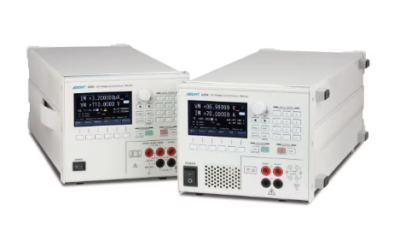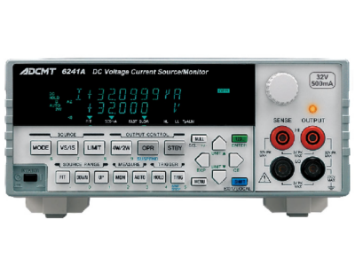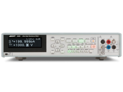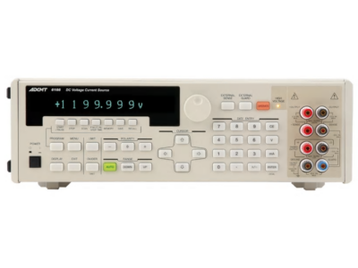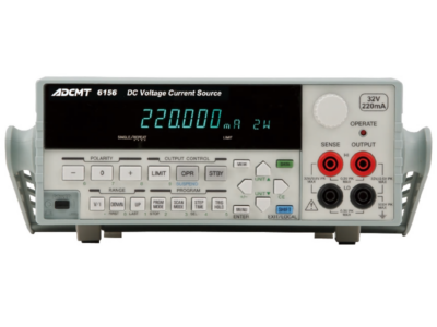


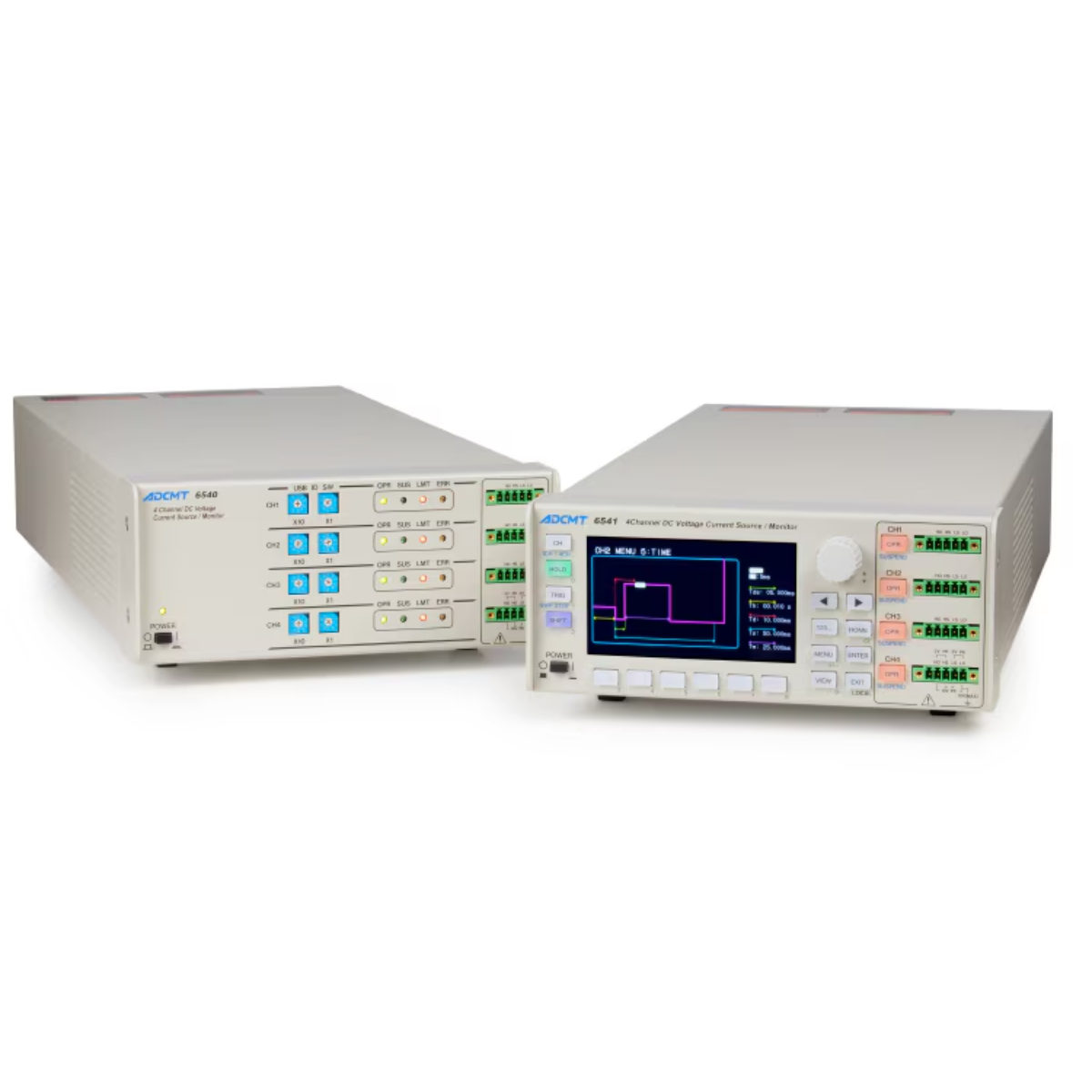

The ADCMT 6540 and 6541 are compact, four-channel DC voltage/current source monitors that combine voltage or current generation with voltage, current and resistance measurement. Each channel supports bipolar sourcing from −10 V to +10 V and up to ±500 mA, with total output current across all four channels limited to ±1 A.
With a basic accuracy of ±0.02%, minimum measurement resolutions of 10 μV and 10 pA, and pulse generation from 50 μs, the instruments are suited to multi-terminal semiconductor devices, battery-management ICs, optical devices and RF front-end modules. Source and measurement timing can be synchronized across channels or multiple instruments.
The 6540 is optimized for production and automated test systems, with four independent USB interfaces and PC control software. The 6541 provides the same core four-channel measurement capability with a 4.3-inch color LCD and front-panel controls for research and development applications.
4 Channels
Independent source and measurement functions
±10 V / ±500 mA
Bipolar output per channel, subject to total-current limits
10 pA
Minimum current measurement resolution
50 μs
Minimum pulse width
Four-Channel Source and Measurement
Select voltage or current sourcing independently from voltage, current or resistance measurement. Four channels in one compact unit simplify testing of devices with multiple terminals and power rails.
Synchronized Multi-Channel Operation
Synchronize measurements during DC output and synchronize both sourcing and measurement during pulse or sweep operation. Each channel can generate the same or a different waveform.
Flexible Source and Sweep Modes
Supports DC, pulse, DC sweep and pulse sweep modes. Fixed, linear, random and two-slope linear sweep patterns enable a wide range of automated device characterization sequences.
Independent HI and LO Limits
Separate high and low compliance settings help protect batteries, capacitors, laser diodes and other devices from over-discharge or unintended reverse-voltage conditions.
Variable Integration and Peak Hold
Integration time can be set from 100 μs to 740 ms for average-current measurements. Peak-hold measurement detects pulse peaks at frequencies up to 20 kHz.
System and Benchtop Configurations
Choose the display-free 6540 for automated test systems or the 6541 with its 4.3-inch color LCD, front-panel controls and optional GPIB or LAN interfaces for laboratory use.
Battery Management IC Evaluation
Apply voltage or current to multiple IC terminals while simultaneously monitoring supply, control and protection responses.
RF Front-End Modules
Provide synchronized, low-noise bias outputs and measure current across multiple supply and control terminals with a single instrument.
LD and PD Bias Testing
Use bipolar voltage or current output as a bias source for laser diodes, photodiodes and optical communication components.
Average and Peak Current Measurement
Characterize pulsed current consumption in wireless devices, displays and other products using variable integration and peak-hold measurements.
Multi-Terminal Semiconductor Devices
Generate synchronized or independent waveforms while measuring multiple terminals of sensors, analog ICs and semiconductor devices.
Automated Production Testing
Integrate four source and measurement channels into inspection systems using USB control, external synchronization and programmable sweeps.
| Specification | 6540 | 6541 |
|---|---|---|
| Number of Channels | 4 | 4 |
| Source Functions | Voltage or current | Voltage or current |
| Measurement Functions | Voltage, current or resistance | Voltage, current or resistance |
| Output Method | Bipolar, source and sink | Bipolar, source and sink |
| Voltage Output | 0 to ±10 V | 0 to ±10 V |
| Voltage Source Resolution | 100 μV | 100 μV |
| Current Output | 0 to ±500 mA per channel* | 0 to ±500 mA per channel* |
| Current Source Resolution | 100 pA | 100 pA |
| Maximum Output Power | 5 W per channel | 5 W per channel |
| Basic Accuracy | ±0.02% typical range | ±0.02% typical range |
| Minimum Voltage Measurement Resolution | 10 μV | 10 μV |
| Minimum Current Measurement Resolution | 10 pA | 10 pA |
| Source Modes | DC, pulse, DC sweep and pulse sweep | DC, pulse, DC sweep and pulse sweep |
| Sweep Types | Fixed, linear, random and two-slope linear | Fixed, linear, random and two-slope linear |
| Minimum Pulse Width | 50 μs | 50 μs |
| Minimum Pulse Cycle | 500 μs; 100 μs without measurement | 500 μs; 100 μs without measurement |
| Variable Integration Time | 100 μs to 740 ms | 100 μs to 740 ms |
| Display | None; LED indicators only | 4.3-inch color LCD |
| USB Interface | Four USB ports; one per channel | One shared USB port |
| Optional Interfaces | — | GPIB and LAN |
| Primary Use | Automated and production test systems | Benchtop research and development |
* Each channel supports up to ±500 mA. The combined current across all four channels is limited to ±1 A. Available sink power and operating temperature are subject to the conditions specified by the manufacturer.