


Compact electrolysis cell analyzer with high-current EIS
Accelerate electrolysis cell development via high-current operational testing
Revolutionizing EIS measurement: Solutions for electrolysis cells and stacks with the ALDAS-Mini
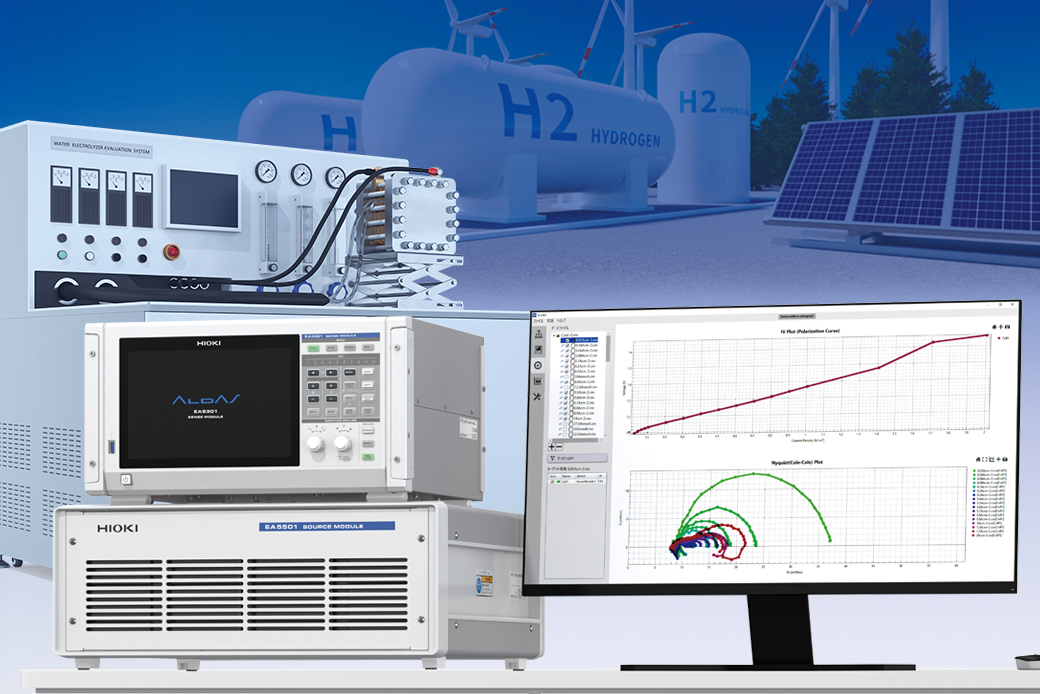
EIS (Electrochemical Impedance Spectroscopy) measurement of electrolysis cells used to face challenges in measuring large cells or cell stacks with high currents. The ALDAS-Mini addresses this issue by enabling EIS measurement for a wide range of cell sizes, from small cells with electrolysis currents of a few amperes to large cells with currents of up to 500 A (*1). Additionally, the system can measure up to 8 cells simultaneously within a cell stack, allowing for comparative analysis of the state of each cell during electrolysis.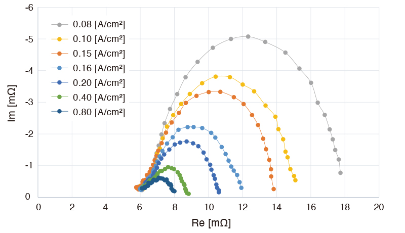
Just simply connect to your existing system
Designed for seamless setup, requiring no modifications to existing systems
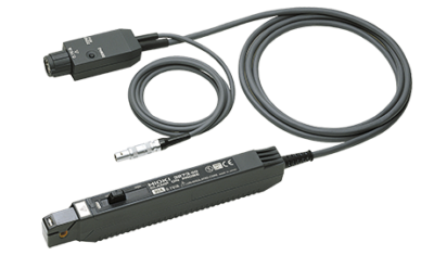
No modification to your electrolysis system is needed to set up the ALDAS-Mini. Unlike conventional booster-equipped FRA (Frequency Response Analyzer) devices, the ALDAS-Mini operates seamlessly alongside the cells' DC power supplies. STEP 1: Applied current connection Connect the SOURCE module to the cell’s power source terminal with the SOURCE Cable. The SOURCE module applies AC current for measurement. STEP 2: Measurement line connection Attach the current sensor to measure the current. Then, connect the SENSE cable to the cell to measure the voltage (both connected to the SENSE module). STEP 3: Start measurement Start the measurement after configuring the necessary settings in the dedicated PC software. The I-V curve and Nyquist plot are displayed simultaneously in real-time, with impedance calculated from the measured current and voltage.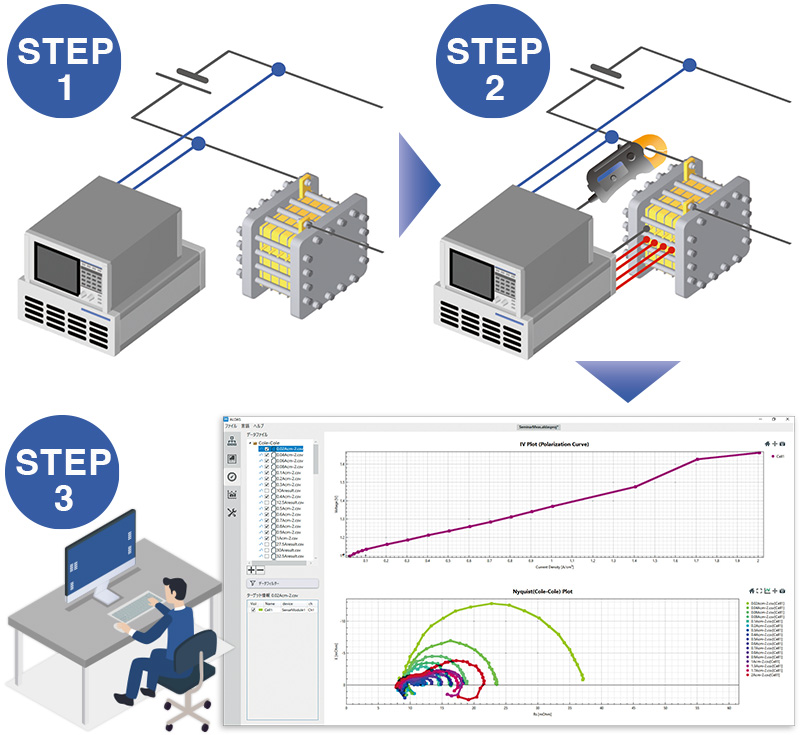
• Evaluation of large cells exceeding 100 cm² • Optimization of hydrogen production • Monitoring cell health and diagnosing degradation factors • Material research
Accuracy guaranteed: 1 year
| Measurement target | Electrolysis cell, cell stack |
| Measurement parameters | Impedance (R,X,θ,Z), voltage (V), current (I) |
| Measurement modes | Logging mode, Nyquist plot mode, Bode plot mode |
| Max. input voltage | 30 V |
| Max. measurable current | 20 A to 500 A (the necessary current sensor will change according to the rated current) If your measurement requirements exceed 500 A, please contact your Hioki representative. |
| Max. measured signal level | 20 Ap-p (at 10 V) |
| Measurement frequency | 0.01 Hz to 10 kHz |
| Number of input channels | Up to 8 channels |
| Dimensions and weight | SENSE Module EA5301 (with 8 channels): approx. 430W × 221H × 361D mm (16.9W × 8.7H × 14.2D in.) (excluding protruding parts), approx. 12.7 kg (28.0 lbs) SOURCE module EA5501: approx. 520W × 197H × 540D mm (20.5W × 7.8H × 21.3D in.) (excluding protruding parts), approx. 27.0 kg (59.5 lbs) (not including cables) |
| Power supply | 100 V to 240 V AC, 50 Hz/60 Hz, 500 VA |
| PC requirements | OS: Windows 11 Interface: wired LAN |