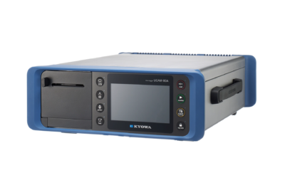


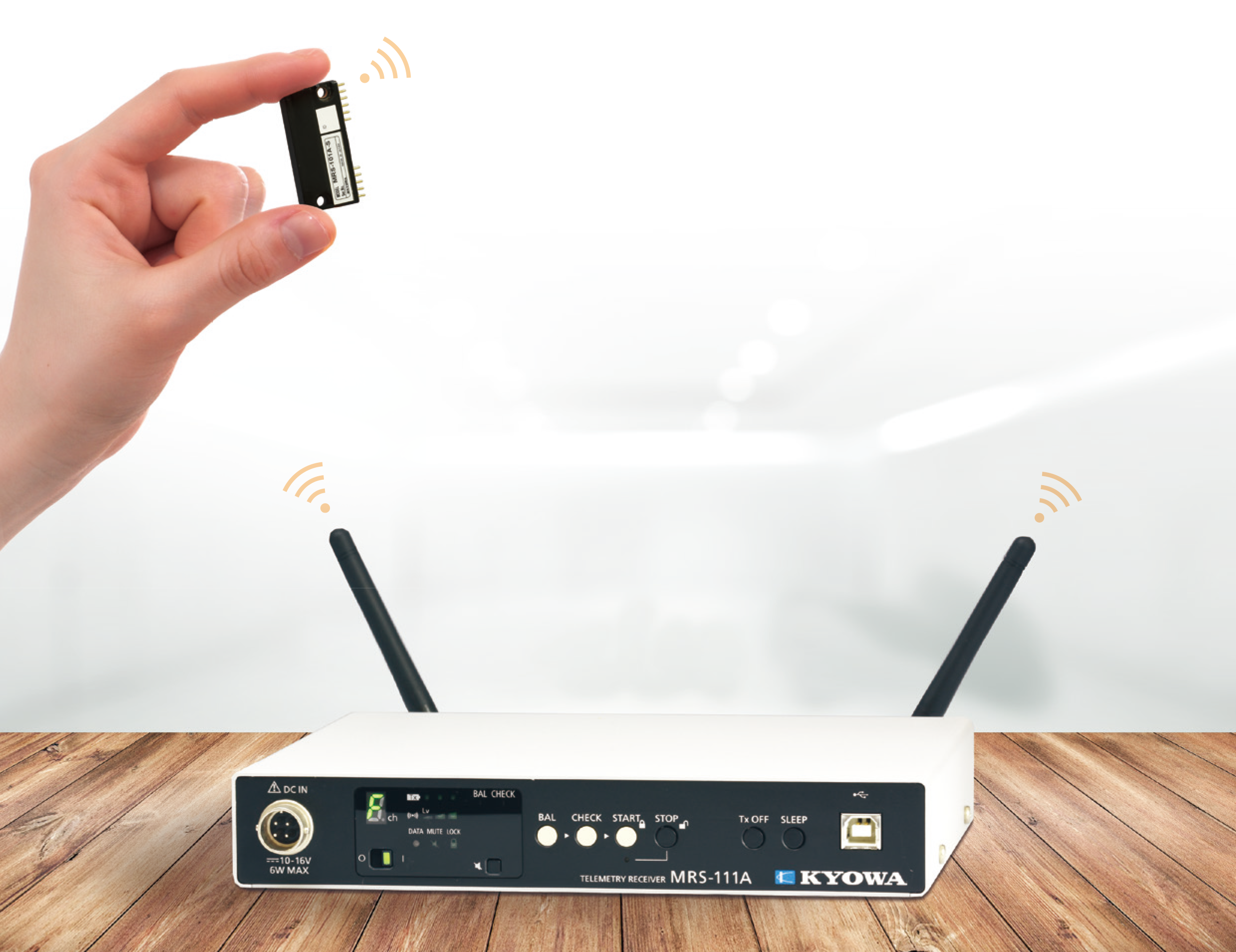

Making Measurement "Wireless" MRS-100 Series
The Digital Telemeter MRS-100 series is a telemeter for various measuring environments, based on the digital modulation system. The MRS-100 series measures data of max. 50 m range (line of sight distance) wirelessly. Compact transmitter and easy installation in narrow space.• Easy operation without PC after initial setting • Quarter-bridge 2-wire system, 3-wire system, and full-bridge system support • Up to 64 channels in a system • Certified in radio law in Japan, the USA, China, India, Thailand, Taiwan, EU (Depends on models) • Hours of continuous use: Max. 34 h (1ch-Strain Transmitter using LR03EJ, AAA cell × 2)
The MRS-100 Series is a lineup of small wireless units that enable to achieve stable communication with digital modulation, and this series can be used to easily make a strain-gage sensor or voltage-output sensor wireless. The MRS-100 Series can therefore be used to respond to rapid events in the automobile-related and other experiment and research fields, and the testing data can be sent almost in real-time. In addition, because the unit can be incorporated into a production line to make the load, pressure, and other sensors used for quality control wireless, it is useful for improving productivity. 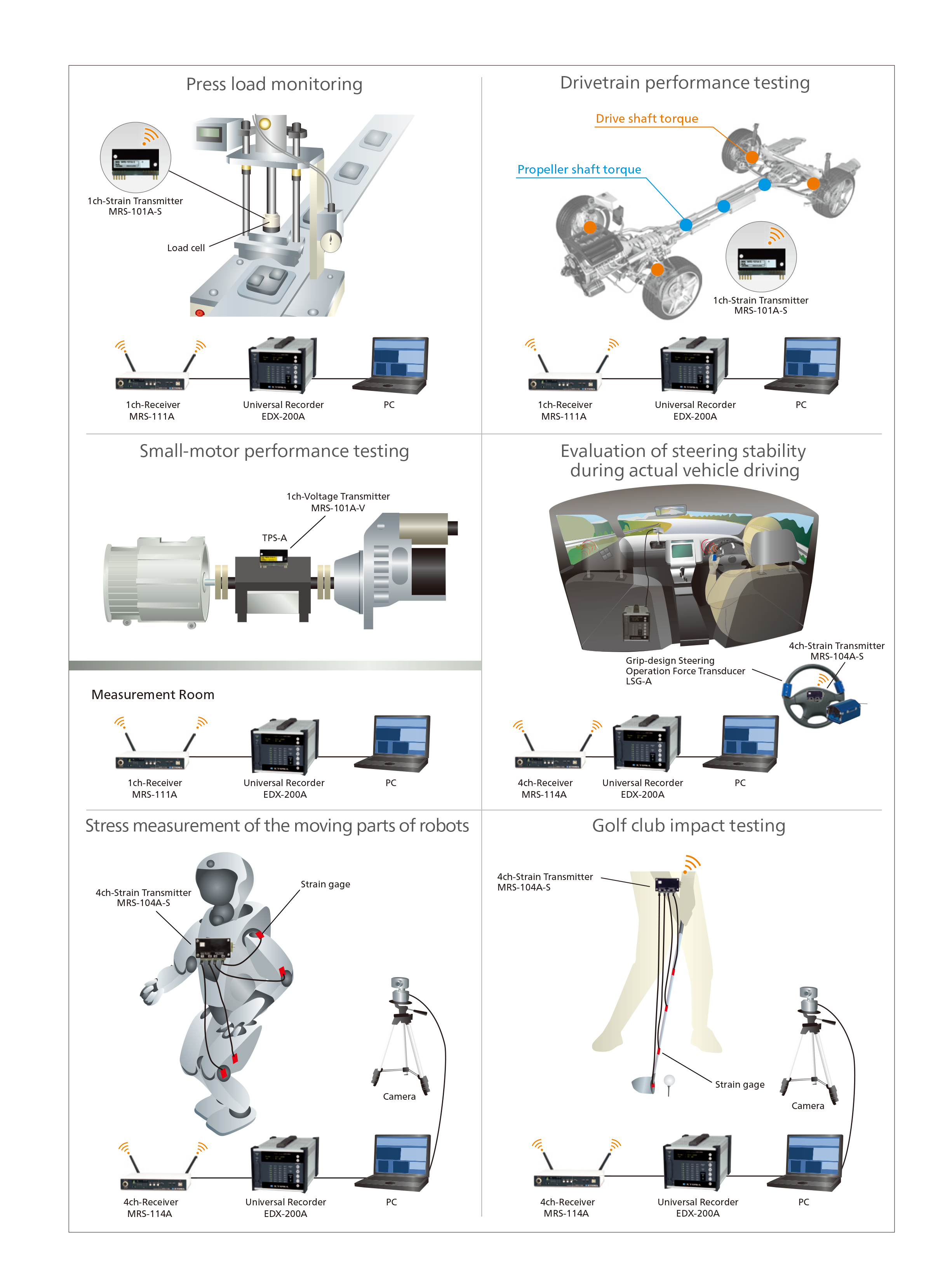
MRS-104A-S 4ch-Strain Transmitter
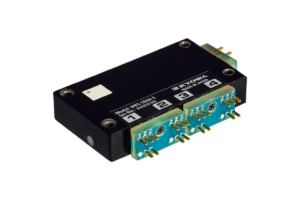
| Measuring Targets | Strain gages (Full bridge system*) Strain-gage transducers*Other bridge systems need bridge box or bridge adapter. |
|---|---|
| Channels | Max. 4 |
| Compatible Bridge Resistance | 120 to 1000 Ω |
| Gage Factor | 2.00 fixed |
| Bridge Excitation | 1 VDC |
| Measuring Range | 1000, 2500, 5000, 10000, 25000 ×10-6 strain |
| Measuring Accuracy | Within ±0.15% FS *The specifications apply to a stable temperature after warm up for about 30 minutes in an 25 ±5℃ environment. |
| Balance Adjustment Range | Within ±10000 ×10-6 strain |
| AD Resolution | 16 bits |
| Sampling Frequencies | 1 channel: 4.8 kHz 2 channels: 3.2 kHz 3 channels: 2.4 kHz 4 channels: 1.92 kHz |
| Temperature Stability | Zero point: Within ±0.05 ×10⁻⁶ strain per °C Sensitivity: Within ±0.01%/°C |
| Operating Temperature | -25 to 75°C *If the ambient temperature exceeds 50°C, it cannot be used in a vibration, shock, centrifugal acceleration by fixing the bolts in the body mounting holes. |
| Operating Humidity | 20 to 85% (Non-condensing) |
| Vibration Resistance | 294.2 m/s2 (30 G), 10 to 500 Hz *If the ambient temperature exceeds 50°C, it cannot be used in a vibration, shock, centrifugal acceleration by fixing the bolts in the body mounting holes. |
| Shock Resistance | 980.7 m/s2 (100 G), 11 ms or less, half sine wave *If the ambient temperature exceeds 50°C, it cannot be used in a vibration, shock, centrifugal acceleration by fixing the bolts in the body mounting holes. |
| Centrifugal Acceleration Resistance | 980.7 m/s2 (100 G) *If the ambient temperature exceeds 50°C, it cannot be used in a vibration, shock, centrifugal acceleration by fixing the bolts in the body mounting ho les. **The specification of centrifugal acceleration is assumed for height (H) direction of the transmitter. Take measures to prevent scattering of the test product, various sensors, and transmitter for safety. |
| Power Supply | 2.2 to 4.4 VDC |
| Current Consumption | Within 62 mA (Test conditions: Power supply 3.0 V, bridge resistance 120 Ω) |
| Hours of Continuous Use | Approx. 12 h [Lithium (CR2 manufactured by Panasonic)] Approx. 10 h [Ni-MH eneloop® (BK-4MCC, AAA cell×2)] Approx. 13 h [Alkaline EVOLTA (LR03EJ, AAA cell×2)] *Test conditions: 23 ±5°C, bridge resistance 120 Ω |
| Dimensions | 55 W × 10 H × 32.5 D mm (Excluding protrusions, with adapter) |
| Weight | Approx. 32 g (With adapter) |
| Compliance | Directive 2014/53/EU (RED) Directive 2011/65/EU, (EU) 2015/863 (10 restricted substances) (RoHS) |
RF Specifications
| Transceiver Frequency Channel | 1 (Choose 1 channel from 16 channels using Setting software) |
|---|---|
| Antennas | Built-in |
| Radio Communication Frequency Band | 2.4 GHz band |
| Radio Certification | Digital modulation system |
| Dimensions | Japan, the USA, China, India, Thailand, Taiwan, EU |
| Communication Distance | 50 m (Max. line of sight distance) |
| Environment of Usage | Environment where the wireless LAN and the Bluetooth?, etc. are not intermingled on the 2.4 GHz. |
| Frequency Channel and Central Frequency | Frequency channel--------------Central frequency (GHz) CH 0--------------------------------2.405 CH 1--------------------------------2.410 CH 2--------------------------------2.415 CH 3--------------------------------2.420 CH 4--------------------------------2.425 CH 5--------------------------------2.430 CH 6--------------------------------2.435 CH 7--------------------------------2.440 CH 8--------------------------------2.445 CH 9--------------------------------2.450 CH A--------------------------------2.455 CH B--------------------------------2.460 CH C--------------------------------2.465 CH D--------------------------------2.470 CH E--------------------------------2.475 CH F--------------------------------2.480Communication is not possible if there are multiple transmitters with the same radio Frequency Channel in the system. |
Combination Specifications of Transmitter with Receiver
| Compatible Receiver | MRS-114A firmware ver. 3.00 or later *No MRS-104A-S be used in combination with a 1-channel receiver. |
|---|---|
| Analog Output Voltage | ±5 V/Full scale range |
| Combination Measuring Accuracy | Within ±0.2% FS |
| Frequency Response | Measuring channel: 1 Sampling frequencies: 4.8 kHz Frequency response: DC to 370 Hz (Deviation +0.5, -1dB), -3 ±1 dB (at 480 Hz)Measuring channels: 2 Sampling frequencies: 3.2 kHz Frequency response: DC to 320 Hz (Deviation +0.5, -1dB), -3 ±1 dB (at 466 Hz)Measuring channels: 3 Sampling frequencies: 2.4 kHz Frequency response: DC to 240 Hz (Deviation +0.5, -1dB), -3 ±1 dB (at 424 Hz)Measuring channels: 4 Sampling frequencies: 1.92 kHz Frequency response: DC to 192 Hz (Deviation +0.5, -1dB), -3 ±1 dB (at 376 Hz) |
| Delay Time | Measuring channel: 1 Sampling frequencies: 4.8 kHz Delay time: 11.1 ±0.3 ms (at DC to 480 Hz)Measuring channels: 2 Sampling frequencies: 3.2 kHz Delay time: 10.8 ±0.3 ms (at DC to 320 Hz)Measuring channels: 3 Sampling frequencies: 2.4 kHz Delay time: 9.8 ±0.3 ms (at DC to 240 Hz)Measuring channels: 4 Sampling frequencies: 1.92 kHz Delay time: 9.7 ±0.3 ms (at DC to 192 Hz)Only 1 transmitter can be used in combination with 1 receiver. No MRS-104A-S be used in combination with a 1-channel receiver. 2 or more measuring channels are for 4-channel transmitter with 4-channel receiver. |
| Standard Accessories | Full-bridge adapter ADP-401 × 2 JCIS10-70 miniature screw (M2 × 4) × 3 Power adapter ADP-40P The above are installed in the transmitter.Fastening bracket × 2 Battery holder (AAA cell × 2) for checking operation ID label |
| Optional Accessories | Quarter-bridge 2-wire adapter (120 Ω) ADP-402-120 (2 channels/pc) Quarter-bridge 3-wire adapter (120 Ω) ADP-403-120 (2 channels/pc) Full-bridge adapter ADP-401 Power adapter ADP-40P MRS 4ch junction kit MRS-J14A |
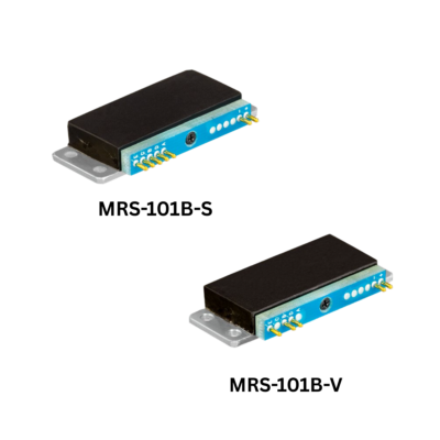
MRS-101B-S 1ch-Strain Transmitter
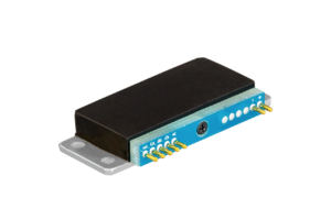
| Measuring Targets | Strain gages (Full bridge system*) Strain-gage transducers*Other bridge systems need bridge box or bridge adapter. |
|---|---|
| Channels | 1 |
| Compatible Bridge Resistance | 120 to 1000 Ω |
| Gage Factor | 2.00 fixed |
| Bridge Excitation | 1 VDC |
| Measuring Range | 1000, 2500, 5000, 10000, 25000 ×10-6 strain |
| Measuring Accuracy | Within ±0.15% FS *The above specifications apply to a stable temperature after warm up at 25 ±5℃ for 30 minutes. |
| Balance Adjustment Range | Within ±10000 ×10-6 strain |
| AD Resolution | 16 bits |
| Sampling Frequencies | 4.8 kHz |
| Temperature Stability | Zero point: Within ±0.05 ×10⁻⁶ strain per °C Sensitivity: Within ±0.01%/°C |
| Operating Temperature | -25 to 75°C |
| Operating Humidity | 20 to 85% (Non-condensing) |
| Vibration Resistance | 294.2 m/s2 (30 G), 10 to 500 Hz |
| Shock Resistance | 980.7 m/s2 (100 G), 11 ms or less, half sine wave |
| Centrifugal Acceleration Resistance | 29420 m/s2 (3000 G) *1, *2 *1 The figures are when installed with our specified screws and torque. *2 Under centrifugal acceleration environment, take measures to prevent scattering of the test product, various sensors, and transmitter for safety |
| Power Supply | 2.2 to 4.4 VDC |
| Current Consumption | Within 32 mA (Test conditions: Power supply 3.0 V, bridge resistance 120 Ω) |
| Hours of Continuous Use | Approx. 28 h [Lithium (CR2 manufactured by Panasonic)] Approx. 24 h [Ni-MH eneloop® (BK-4MCC, AAA cell×2)] Approx. 34 h [Alkaline EVOLTA (LR03EJ, AAA cell×2)]*Test conditions: 23 ±5°C, bridge resistance 120 Ω |
| Dimensions | 47 W × 7 H × 20 D mm (Excluding protrusions, with adapter) |
| Weight | Approx. 17 g (With adapter) |
| Compliance | Directive 2014/53/EU (RED) Directive 2011/65/EU, (EU)2015/863 (10 restricted substances) (RoHS) |
RF Specifications
| Transceiver Frequency Channel | 1 (Choose 1 channel from 16 channels using Setting software) |
|---|---|
| Antennas | Built-in |
| Radio Communication Frequency Band | 2.4 GHz band |
| Radio Certification | Digital modulation system |
| Dimensions | Japan, the USA, China, India, Thailand, Taiwan, EU |
| Communication Distance | 50 m (Max. line of sight distance) |
| Environment of Usage | Environment where the wireless LAN and the Bluetooth?, etc. are not intermingled on the 2.4 GHz. |
| Frequency Channel and Central Frequency | Frequency channel--------------Central frequency (GHz) CH 0--------------------------------2.405 CH 1--------------------------------2.410 CH 2--------------------------------2.415 CH 3--------------------------------2.420 CH 4--------------------------------2.425 CH 5--------------------------------2.430 CH 6--------------------------------2.435 CH 7--------------------------------2.440 CH 8--------------------------------2.445 CH 9--------------------------------2.450 CH A--------------------------------2.455 CH B--------------------------------2.460 CH C--------------------------------2.465 CH D--------------------------------2.470 CH E--------------------------------2.475 CH F--------------------------------2.480Communication is not possible if there are multiple transmitters with the same radio Frequency Channel in the system. |
Combination Specifications of Transmitter with Receiver
| Compatible Receiver | MRS-114A Firmware Ver. 3.01 or later MRS-111A (-E) Firmware Ver. 3.01 or later MRS-111B Firmware Ver. 3.01 or later |
|---|---|
| Analog Output Voltage | ±5 V/Full scale range |
| Combination Measuring Accuracy | Within ±0.2% FS |
| Frequency Response | DC to 370 Hz (Deviation +0.5, -1 dB) -3 ±1 dB (at 480 Hz) |
| Delay Time | 11.1 ±0.3 ms (at DC to 480 Hz) Only 1 transmitter can be used in combination with 1 receiver. |
| Standard Accessories | Full-bridge adapter ADP-11S JCIS10-70 miniature screw (M2 × 4) The above are installed in the transmitter.Battery holder (AAA cell × 2) for checking operation ID label |
| Optional Accessories | MRS junction kit MRS-J11B Quarter-bridge 2-wire adapter (120 Ω) ADP-12S-120 Full-bridge adapter ADP-11S |
MRS-101B-T 1ch-Thermocouple Transmitter
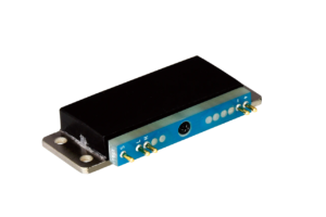
| Measuring Targets | Thermocouples |
|---|---|
| Channels | 1 |
| Compatible Bridge Resistance | K, T, N, J (Resistance of thermocouple: 500 Ω or less) |
| Measuring Range | K1300: -200 to 1300ºC K500: -200 to 500ºC K100: -100 to 100ºC T400: -200 to 400ºC T100: -100 to 100ºC N1300: -200 to 1300ºC N500: -200 to 500ºC N100: -100 to 100ºC J1200: -200 to 1200ºC J500: -200 to 500ºC J100: -100 to 100ºC |
| Range Accuracy | Ambient temperature: 20 to 30ºC Measuring temperature: Below -50ºC Telemeter measuring accuracy (internal reference compensation mode): Within ±0.4%rdg ±2.0ºCAmbient temperature: 20 to 30ºC Measuring temperature: -50ºC or more Telemeter measuring accuracy (internal reference compensation mode): Within ±0.1%rdg ±1.5ºCAmbient temperature:0 to 50ºC Measuring temperature: Below -50ºC Telemeter measuring accuracy (internal reference compensation mode): Within ±0.4%rdg ±2.8ºCAmbient temperature: 0 to 50ºC Measuring temperature: -50ºC or more Telemeter measuring accuracy (internal reference compensation mode): Within ±0.1%rdg ±2.5ºCAmbient temperature:-25 to 75ºC Measuring temperature: Below -50ºC Telemeter measuring accuracy (internal reference compensation mode): Within ±0.4%rdg ±3.8ºC Ambient temperature: -25 to 75ºC Measuring temperature: -50ºC or more Telemeter measuring accuracy (internal reference compensation mode): Within ±0.1%rdg ±3.5ºC * The input terminal temperature is in equilibrium. * The above specifications apply to a stable temperature after warm up for about 60 minutes. |
| Check Function | Burnout check |
| AD Resolution | 16 bits |
| Sampling Frequencies | 50 Hz |
| Operating Temperature | -25 to 75°C |
| Operating Humidity | 20 to 85% (Non-condensing) |
| Vibration Resistance | 294.2 m/s2 (30 G), 10 to 500 Hz |
| Shock Resistance | 980.7 m/s2 (100 G), 11 ms or less, half sine wave |
| Centrifugal Acceleration Resistance | 29420 m/s2 (3000 G) * The figures are when installed with our specified screws and torque. * Under centrifugal acceleration environment, take measures to prevent scattering of the test product, various sensors, and transmitter for safety. |
| Power Supply | 2.2 to 4.4 VDC |
| Current Consumption | Within 24 mA (Test conditions: Power supply 3.0 V) |
| Hours of Continuous Use | Approx. 33 h [Lithium (CR2 manufactured by Panasonic)] Approx. 30 h [Ni-MH eneloop® (BK-4MCC, AAA cell×2)] Approx. 45 h [Alkaline EVOLTA (LR03EJ, AAA cell×2)]*Test conditions :23 ±5ºC |
| Dimensions | 47 W × 7 H × 20 D mm (Excluding protrusions, with adapter) |
| Weight | Approx. 17 g (With adapter) |
| Compliance | Directive 2014/53/EU (RED) Directive 2011/65/EU, (EU)2015/863 (10 restricted substances) (RoHS) |
RF Specifications
| Transceiver Frequency Channel | 1 (Choose 1 channel from 16 channels using Setting software) |
|---|---|
| Antennas | Built-in |
| Radio Communication Frequency Band | 2.4 GHz band |
| Radio Certification | Digital modulation system |
| Dimensions | Japan, the USA, China, India, Thailand, Taiwan, EU |
| Communication Distance | 50 m (Max. line of sight distance) |
| Environment of Usage | Environment where the wireless LAN and the Bluetooth?, etc. are not intermingled on the 2.4 GHz. |
| Frequency Channel and Central Frequency | Frequency channel--------------Central frequency (GHz) CH 0--------------------------------2.405 CH 1--------------------------------2.410 CH 2--------------------------------2.415 CH 3--------------------------------2.420 CH 4--------------------------------2.425 CH 5--------------------------------2.430 CH 6--------------------------------2.435 CH 7--------------------------------2.440 CH 8--------------------------------2.445 CH 9--------------------------------2.450 CH A--------------------------------2.455 CH B--------------------------------2.460 CH C--------------------------------2.465 CH D--------------------------------2.470 CH E--------------------------------2.475 CH F--------------------------------2.480Communication is not possible if there are multiple transmitters with the same radio Frequency Channel in the system. |
Combination Specifications of Transmitter with Receiver
| Compatible Receiver | MRS-114A Firmware Ver. 3.01 or later MRS-111A (-E) Firmware Ver. 3.01 or later MRS-111B Firmware Ver. 3.01 or later |
|---|---|
| Analog Output Voltage | ±5 V/Full scale range |
| Combination Measuring Accuracy | Within ±0.2% FS |
| Frequency Response | DC to 370 Hz (Deviation +0.5, -1 dB) -3 ±1 dB (at 480 Hz) |
| Delay Time | 11.1 ±0.3 ms (at DC to 480 Hz) Only 1 transmitter can be used in combination with 1 receiver. |
| Standard Accessories | Full-bridge adapter ADP-11S JCIS10-70 miniature screw (M2 × 4) The above are installed in the transmitter.Battery holder (AAA cell × 2) for checking operation ID label |
| Optional Accessories | MRS junction kit MRS-J11B Quarter-bridge 2-wire adapter (120 Ω) ADP-12S-120 Full-bridge adapter ADP-11S |