Motor torque fundamentals
What Is Cogging Torque, and Why Does It Matter?
Cogging torque is the periodic torque variation produced by magnetic attraction between the rotor magnets and stator teeth in a permanent-magnet motor when the motor is not energized. It can contribute to uneven rotation, noise, vibration, and disturbances that become important in precision motion and high-efficiency motor design.
Cogging Torque
Measured with the motor non-energized while the shaft is rotated through angular position. The goal is to characterize magnetic torque variation independently from drive-current effects.
Torque Ripple
Measured while the motor is energized and driven. Torque ripple reflects periodic output-torque variation created by the combined motor electromagnetic design and control behavior.
Noise & Vibration
Periodic torque variation can excite mechanical structures and contribute to audible noise or vibration. Measuring the angular waveform helps engineers identify where the variation occurs.
Motor Control Development
When torque data is correlated with electrical or position signals, engineers can compare commutation, control settings, rotor position, and other factors against the measured torque waveform.
ATM-100 / ATV-100 proof points
High-Resolution Angular Torque Measurement for Motor Development
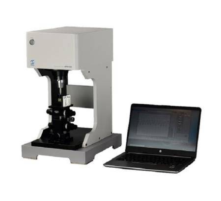
Sugawara's ATM-100 and ATV-100 systems are designed specifically for cogging-torque and torque-ripple evaluation. Their vertically arranged torque-sensor configuration simplifies shaft alignment and avoids axle-bearing loss inside the torque sensor.
0.01°Maximum angular resolution
36,000Maximum data points per revolution
±0.5%Torque accuracy of rated torque after calibration
As little as 3 sMeasurement time at 20 r/min under the stated test condition
Measurement method
How Cogging Torque and Torque Ripple Are Measured
The ATM-100 / ATV-100 rotates the motor through a controlled angular position while a selected torque sensor captures the torque waveform. The test speed can be set from 0.1 to 20 r/min. Lower rotational speeds provide denser angular sampling, reaching 36,000 points per revolution at 0.01° intervals.
Vertical Torque-Sensor Arrangement
The vertical sensor arrangement uses no axle bearings in the torque sensor, reducing a potential source of mechanical-loss error and simplifying alignment of the motor shaft with the sensor shaft.
Interchangeable Torque Sensors
Five sensor ranges are available across the ATM-100 / ATV-100 platform: 1 mN·m, 10 mN·m, 100 mN·m, 1 N·m, and 10 N·m.
Angle-Based Waveform
Torque is evaluated against angular position so periodic behavior can be inspected directly rather than reduced to only a single average or peak number.
Repeatable Test Setup
ATM-100 includes an XYZ stage, while ATV-100 uses a larger standard motor fixture. Custom jigs and couplings can be considered according to motor geometry and torque characteristics.
System selection
ATM-100 vs. ATV-100: Choose by Torque Range and Motor Size
The two testers share the same basic measurement concept but cover different torque ranges and fixture sizes. Use the expected torque level and motor geometry as the first selection criteria.
| Selection item |
ATM-100 |
ATV-100 |
| Torque sensor ranges |
1 mN·m / 10 mN·m / 100 mN·m |
1 N·m / 10 N·m |
| Sensor shaft diameter |
φ3 mm |
φ10 mm |
| Torque accuracy |
±0.5% of rated torque after calibration with ATM-100 / ATV-100 |
| Rotation speed |
0.1–20 r/min, adjustable in 0.1 r/min increments |
| Angle resolution |
0.01° maximum resolution |
| Typical fixture approach |
XYZ stage for smaller / lower-torque motor alignment |
Larger standard motor fixture for N·m-level applications |
TORQuick CT analysis
XY, Polar, and FFT Analysis for Torque Waveforms
TORQuick CT is Sugawara's motor-evaluation software for ATM-100 and ATV-100. It provides multiple views of the measured torque waveform so engineers can inspect periodic behavior and analyze frequency components rather than relying only on one numeric torque value.
XY Coordinate Graph
Review torque versus angular position to locate peaks, valleys, and repeating torque patterns over the motor revolution.
Polar Coordinate Graph
Visualize torque behavior around the motor's rotational cycle, which can make repeating angular patterns easier to interpret.
FFT Analysis
Use frequency analysis to identify dominant periodic components and compare changes between motor designs, assembly conditions, or control settings.
External Signal Overlay
With the optional I/O module, up to eight external channels can be displayed with angle-torque characteristics. Signals may include voltage, current, temperature, or motor-position data.
How to specify the test
What to Confirm Before Selecting a Cogging Torque Tester
Accurate cogging-torque testing depends on more than the torque range. Motor shaft geometry, fixture rigidity, alignment, energized or non-energized operating state, angular sampling, and any electrical or position signals required for correlation should all be defined before the test system is specified.
| Selection factor |
What to confirm |
Why it matters |
| Torque magnitude |
Expected peak and typical cogging / ripple torque |
Determines the appropriate TSA sensor range and whether ATM-100 or ATV-100 is suitable. |
| Motor geometry |
Shaft diameter, protruding shaft length, mounting points, overall size |
Defines fixture, coupling, and alignment requirements. |
| Measurement state |
Non-energized cogging torque or energized torque ripple |
Determines the test setup and whether synchronized motor power control is required. |
| Angular detail |
Required angular resolution and data density |
Lower rotation speed provides denser sampling, up to 36,000 points per revolution. |
| Analysis requirement |
Waveform comparison, polar plot, FFT, peak-count analysis |
Defines how the torque waveform will be interpreted during design or quality evaluation. |
| External signals |
Voltage, current, temperature, resolver / Hall / position data |
Optional I/O enables correlation of torque behavior with motor-control and operating signals. |
Related motor testing solutions
Cogging torque and torque ripple answer a specific angular-torque question. Use the related Solution pages when the engineering requirement shifts to loaded torque-speed performance, ultra-high-speed operation, stepper-motor pull-in / pull-out behavior, or environmental testing.
Frequently asked questions
Cogging Torque & Torque Ripple Testing FAQ
What is the difference between cogging torque and torque ripple?
Cogging torque is periodic torque variation caused mainly by magnetic interaction between rotor magnets and stator teeth and is measured with the motor non-energized. Torque ripple is periodic output-torque variation while the motor is energized and operating, so drive and control behavior can also affect the result.
Which motors can be tested with ATM-100 / ATV-100?
Sugawara describes the systems for DC motors, BLDC motors, AC servo motors, stepping motors, and other applications that fit the available torque-sensor and fixture ranges.
What torque ranges are available?
ATM-100 supports 1 mN·m, 10 mN·m, and 100 mN·m sensors. ATV-100 supports 1 N·m and 10 N·m sensors.
What is the maximum angular resolution?
The maximum angular resolution is 0.01°. At 0.1 to 1.5 r/min, the system can collect up to 36,000 data points per revolution at 0.01° intervals.
How fast can a measurement be completed?
Sugawara states that a measurement can be completed in as little as approximately 3 seconds when the tester is operated at 20 r/min. Actual test time depends on the selected measurement conditions and workflow.
Can electrical or position signals be compared with torque?
Yes. With the optional I/O module, external channels can be displayed with angle-torque characteristics. Examples include voltage, current, temperature, resolver, Hall-sensor, or motor-position signals.
What information should I provide for a cogging torque or torque-ripple test system?
Provide the motor type, expected torque range, shaft and mounting dimensions, energized or non-energized test objective, required angular resolution, target analysis method, external signals to be recorded, and whether custom fixtures or couplings are needed.
U.S. application support
Discuss Your Cogging Torque or Torque Ripple Application
Share the motor type, expected torque range, shaft dimensions, measurement objective, angular-analysis requirement, and any external signals that need to be correlated. Denkei Corporation Americas can help identify a suitable Sugawara ATM-100 / ATV-100 configuration.
Discuss Your Motor Testing Application